As-built drawings are an integral part of the construction process. It compares the final structure with the original plan and tracks any changes. Now, suppose there exists a building with no proper as-built drawings or documentation. The building is supposed to undergo renovation or maintenance. Since As-built drawings are crucial for renovation and maintenance projects, the contractors will have a hard time dealing with the process. This is where the Scan-to-BIM point cloud technology comes in.
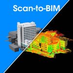
The term Scan-to-BIM means exactly how it sounds. The main goal is to scan the existing building into a soft form. But how is it done? A 3D laser scanning device is used to collect data in the form of “points.” These points represent the existing condition of the building and number in millions. Millions of these points merge to form a Point Cloud scan. This point cloud scan is then imported into a 3D modeling software to create the desired as-built drawing/model.
This Scan-to-BIM technology can be used for various purposes like site inspection, design check, create as-built drawings, and documentation, renovation and maintenance of an already made building. The documentation process of an already made building can be divided into four levels.
Level 1: Floor plans
Level 2: Elevation and Roof plans
Level 3: Section plans
Level 4: Site layout plan
The process of implementing the use of Scan-to-BIM can prove to be hard. The process is divided into four steps:
Information Collection:
In the first step, you collect as much data from the site and client as you can. The process includes defining the Scope of Work, Level of Detail and a schedule for the project. The Scope of Work will set the boundaries of the project and what it entails. The process is further divided into two steps, Pre-mobilization considerations and On-site information. Pre-mobilization considerations include the pre-requisites required to complete the process like selecting the 3D laser scanner and project planning. The on-site information includes gathering and confirming the existing conditions of the building.
Processing:
After the data is collected using the 3D laser scanner, next you process that data. This step is very crucial in which you have to validate the collected data, despite its accuracy. You should always cross-check the data to check for any errors. Errors in the continuity of the data may be present due to different environmental conditions that are not detected by the internal system. You should always keep a saved copy of your data before any processing. After this step is the post-processing alignment of the data. Different tools can be used for aligning the data like best fit, ortho, geo-referencing, etc. There will always be confusing data in the point cloud scan that will make the aligning challenging. Different types of point cloud file types are:
- OBJ
- PLY: Polygon File Format or Stanford Triangle Format
- XYZ: X, Y, Z representing the Cartesian coordinates
- PCG, RCS, RCP
- E57
Modeling:
In this step, the scanned points of the project are given a shape or form using 3D Modeling software. Lets take the example of Autodesk REVIT, since it is commonly used. Before you start modeling, you have to verify the coordinates of the point cloud. This can be done using tools like Edge wise, Point Sense, Building scan to BIM, etc. After the coordinates are verified, insert the data into the modeling software. If there are more than one point cloud files then check the coordinates of all of them. After inserting the file, make sure to lock it using the pin tool to a specific location. Create worksets for each point cloud file. When you are modeling, you have to keep a few things in mind.
- Every element must be modeled as a single Revit Element.
- Always use a group of single columns instead of a generic model.
- The walls of the model must fit the Point cloud by cutting thin view angles in Plan and Section view.
Keep in mind that all the participants or stakeholders involved must have access to the same storage disc. Otherwise, everyone will save the files onto their own system.
Quality Check
To make sure that the model is of good quality, run a few rounds of model check by throwing a section and moving it around the project. Use the visibility and override tools to check on some elements. Check the clashes between MEP disciplines using Autodesk Navisworks. It makes it easier for you to move around a Revit model.
Conclusion
To summarize it all, the Scan-to-BIM point cloud feature is one of the newest features used by architects and engineers to create as-built drawings or models of existing structures. This is done using a 3D laser scanner that scans the building and collects data in the form of points. The point cloud files are then processed and modeled using various techniques. This results in a 3D model of the building. The process ends with checking the model for any errors and clashes.